






Metal forming poses immense challenges for machine designers, including high prototyping costs, material waste, and the risk of errors associated with manual machine setup.
When choosing a manufacturer for advanced 3D components, it pays to partner with a supplier that executes processes digitally. An integrated CAD/CAM environment revolutionizes the 3D production of wire and tube elements, eliminating the risk of costly mistakes right at the source—well before the multi-axis CNC bending machine is physically started.
Eliminating 3D Collisions – how Does a Digital Twin Work?
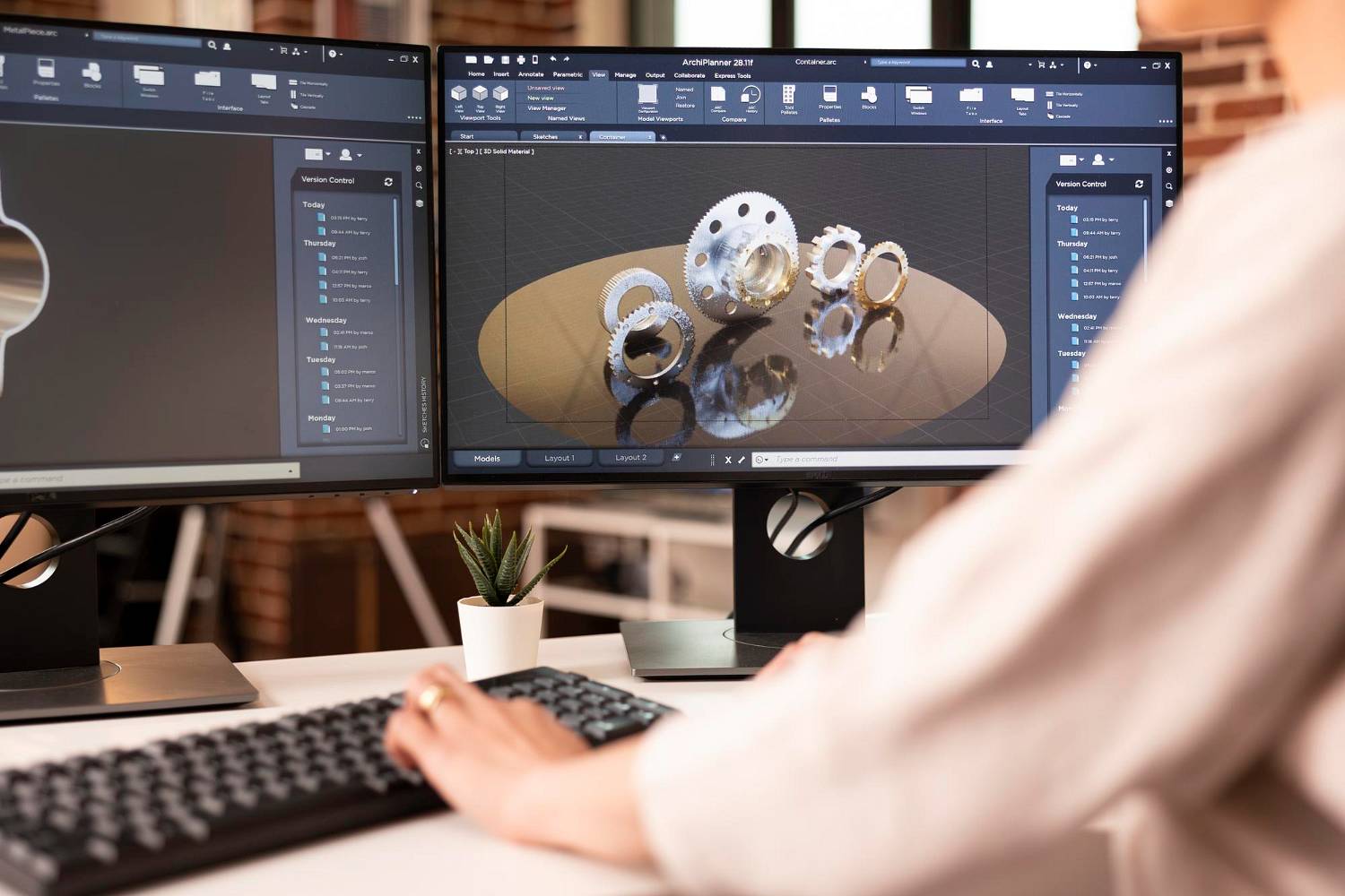
Traditional 3D bending using a trial-and-error approach generated huge material losses. Modern engineering relies on integrating CAD systems (responsible for parametric solid modeling) with CAM systems (controlling the machinery directly). A crucial element of this process is the advanced role of machine simulation.
The virtual CAM environment acts as a “digital twin” of the physical process. In just a few seconds, the software executes thousands of bending simulations in computer memory. The algorithm precisely analyzes every millimeter of the motion trajectory, detecting potential machine collisions—such as the formed wire striking the bending head, gripper, or machine frame. As a result, the operator avoids damaging expensive tooling, and a verified, error-free NC code is delivered straight to the shop floor.
Springback Compensation – the Secret to the Perfect Angle
One of the most challenging problems in bending physics is springback. Once the pressure is released, every metal tends to partially return to its original shape, depending on its modulus of elasticity, grade, and specific batch of steel.
The modern CAD/CAM process eliminates this issue by calculating the K-factor and automatically adjusting the CNC axis control parameters. The machine overbends the material by a precisely calculated margin, ensuring that the component reaches its ideal nominal angle upon releasing the pressure. This automation guarantees uncompromising series repeatability that is impossible to achieve in conventional machine shops.
Conventional Production vs. Integrated CAD/CAM Process
|
Feature |
Traditional Processing (Trial & Error) |
Advanced CAD/CAM Environment |
|
Production Lead Time |
Long (requires manual setups and test runs) |
Instant (code generated directly from a STEP/IGES file) |
|
Risk of Machine Collision |
High (depends entirely on operator attention) |
Zero (automatic verification of the 3D working zone) |
|
Dimensional Accuracy |
Variable (requires manual adjustments after testing) |
Digital (automatic springback compensation) |
|
Series Repeatability |
Dependent on tool wear and wire/pipe batches |
Uncompromising (continuous monitoring of process parameters) |
FAQ – Frequently Asked Questions
-
In which file formats is it best to submit 3D designs?
For technological verification and automatic import of CAM paths, it is best to send universal solid files in STEP or IGES formats. For more technical details regarding file specifications and available machinery, please visit https://mtlpl.eu/en/oferta/2d-and-3d-formed-wire-parts/ -
How does the CAM system handle different wire hardnesses within a single batch?
Modern CNC bending machines at Metalpol work alongside CAM software equipped with active measurement sensors. The machine can measure the material’s resistance force during the first bend and adjust the angle in real-time, matching it to the wire’s current elasticity parameters. -
Does CAD/CAM technology allow thin-walled tubes to be bent without deformation?
Yes. By accurately simulating material stretch in CAM, the appropriate tooling is selected (e.g., internal mandrels and wiper dies), maintaining a perfectly round pipe cross-section without wrinkles or necking.